Home

Igazán kanapé Szennyezett heat pump ts diagram Labe elefánt elhasznál

A vapor-compression heat pump system uses Refrigerant 134a as the working  fluid. The refrigerant enters the compressor at 0.24 MPa, 0 C, with a  volumetric flow rate of 0.6 m 3 /min.
A vapor-compression heat pump system uses Refrigerant 134a as the working fluid. The refrigerant enters the compressor at 0.24 MPa, 0 C, with a volumetric flow rate of 0.6 m 3 /min.

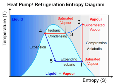
Heat pump and refrigeration cycle - Wikipedia

STEPS: Technology description

T-S diagram of the improved model heat pump cycle for R134a/R245fa (33/67)  | Download Scientific Diagram
T-S diagram of the improved model heat pump cycle for R134a/R245fa (33/67) | Download Scientific Diagram
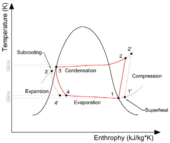
T-S diagram of process of the cascade heat pump | Download Scientific  Diagram
T-S diagram of process of the cascade heat pump | Download Scientific Diagram

Transcritical CO2 heat pump | Industrialheatpumps.nl

a) P-h diagram and (b) T-s diagram of standard heat pump cycle. | Download  Scientific Diagram
a) P-h diagram and (b) T-s diagram of standard heat pump cycle. | Download Scientific Diagram

Representation of a real heat pump cycle in a T-s diagram [3]. | Download  Scientific Diagram
Representation of a real heat pump cycle in a T-s diagram [3]. | Download Scientific Diagram

T-s diagram for heat pump cycle. | Download Scientific Diagram

Ch10, Lesson D, Page 3 - Carnot Heat Pump Cycle

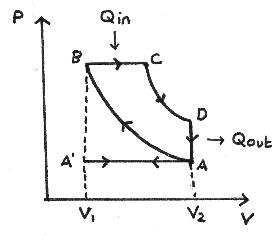
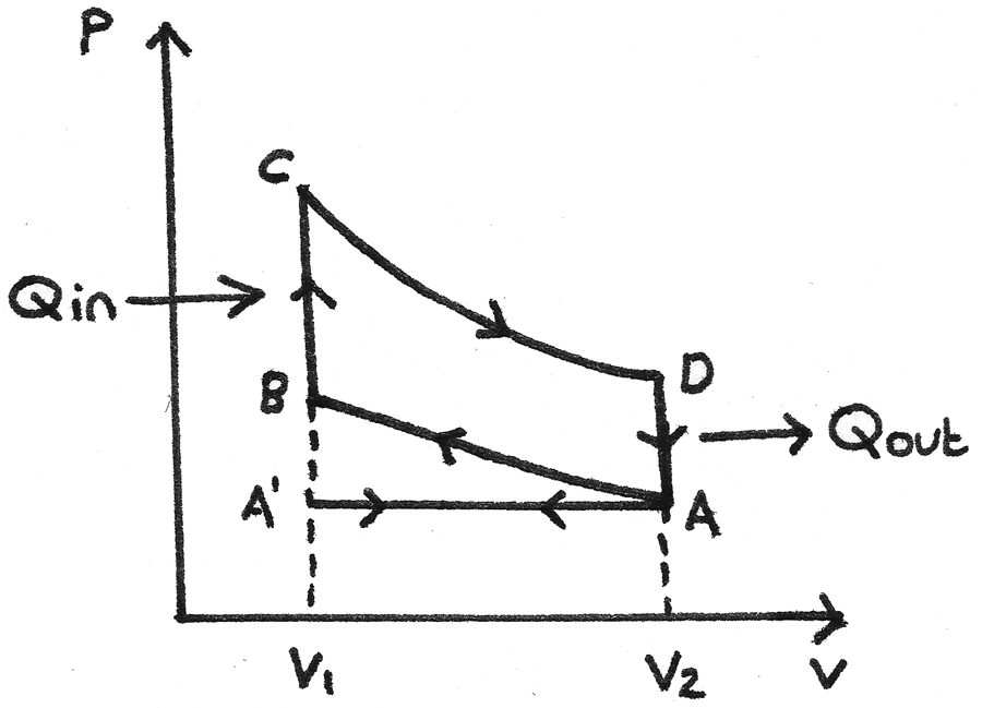
Heat Engines
Heat Engines

Energies | Free Full-Text | Numerical Simulation of Operating Parameters of  the Ground Source Heat Pump
Energies | Free Full-Text | Numerical Simulation of Operating Parameters of the Ground Source Heat Pump

Engines and Heat Pumps - Revise.im

Applications of Thermodynamics: Heat Pumps and Refrigerators | Physics

Heat Engines
Heat Engines

The T-S diagram of a theoretical heat pump cycle for: (a) Zeotropic... |  Download Scientific Diagram
The T-S diagram of a theoretical heat pump cycle for: (a) Zeotropic... | Download Scientific Diagram

Mechanical Engineering Thermodynamics - Lec 7, pt 3 of 3: Carnot  Refrigerator / Heat Pump - YouTube
Mechanical Engineering Thermodynamics - Lec 7, pt 3 of 3: Carnot Refrigerator / Heat Pump - YouTube

Engines and Heat Pumps - Revise.im

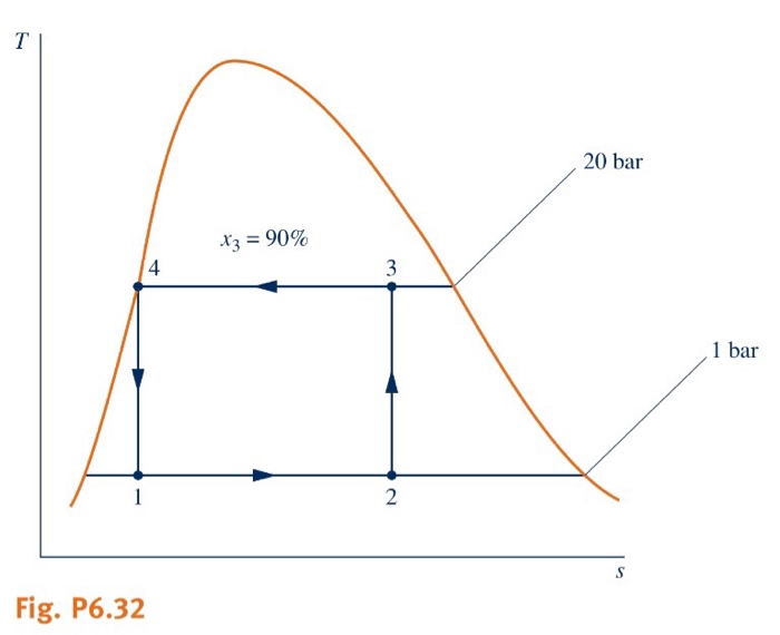
Figure provides the T-s diagram of a Carnot heat pump cycle for which the  substance in ammonia. Determine the net work input required, in kJ, for 50  cycles of operation and 0.1
Figure provides the T-s diagram of a Carnot heat pump cycle for which the substance in ammonia. Determine the net work input required, in kJ, for 50 cycles of operation and 0.1

Ch10, Lesson D, Page 4 - Heat Pump Effciency

T-S diagram of heat pump cycle[6]. T-s diagram of heat pump cycle is... |  Download Scientific Diagram
T-S diagram of heat pump cycle[6]. T-s diagram of heat pump cycle is... | Download Scientific Diagram
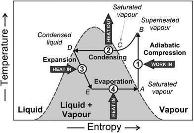
A review of domestic heat pumps - Energy & Environmental Science (RSC  Publishing) DOI:10.1039/C2EE22653G
A review of domestic heat pumps - Energy & Environmental Science (RSC Publishing) DOI:10.1039/C2EE22653G

Property diagrams TS and PH for refrigeration - YouTube

Performance and economic evaluation of a photovoltaic/thermal (PV/T)-cascade  heat pump for combined cooling, heat and power in tropical climate area -  ScienceDirect
Performance and economic evaluation of a photovoltaic/thermal (PV/T)-cascade heat pump for combined cooling, heat and power in tropical climate area - ScienceDirect

Solved 6.32 Figure P6.32 provides the T-s diagram of a | Chegg.com

The figure below provides the T-s diagram of a Carnot heat pump cycle for  which the substance is ammonia. Determine the net work input required, in  kJ, for 50 cycles of operation
The figure below provides the T-s diagram of a Carnot heat pump cycle for which the substance is ammonia. Determine the net work input required, in kJ, for 50 cycles of operation